How to Upgrade Your Garage or Shop Lighting
Learn how to add more light in this illuminating post
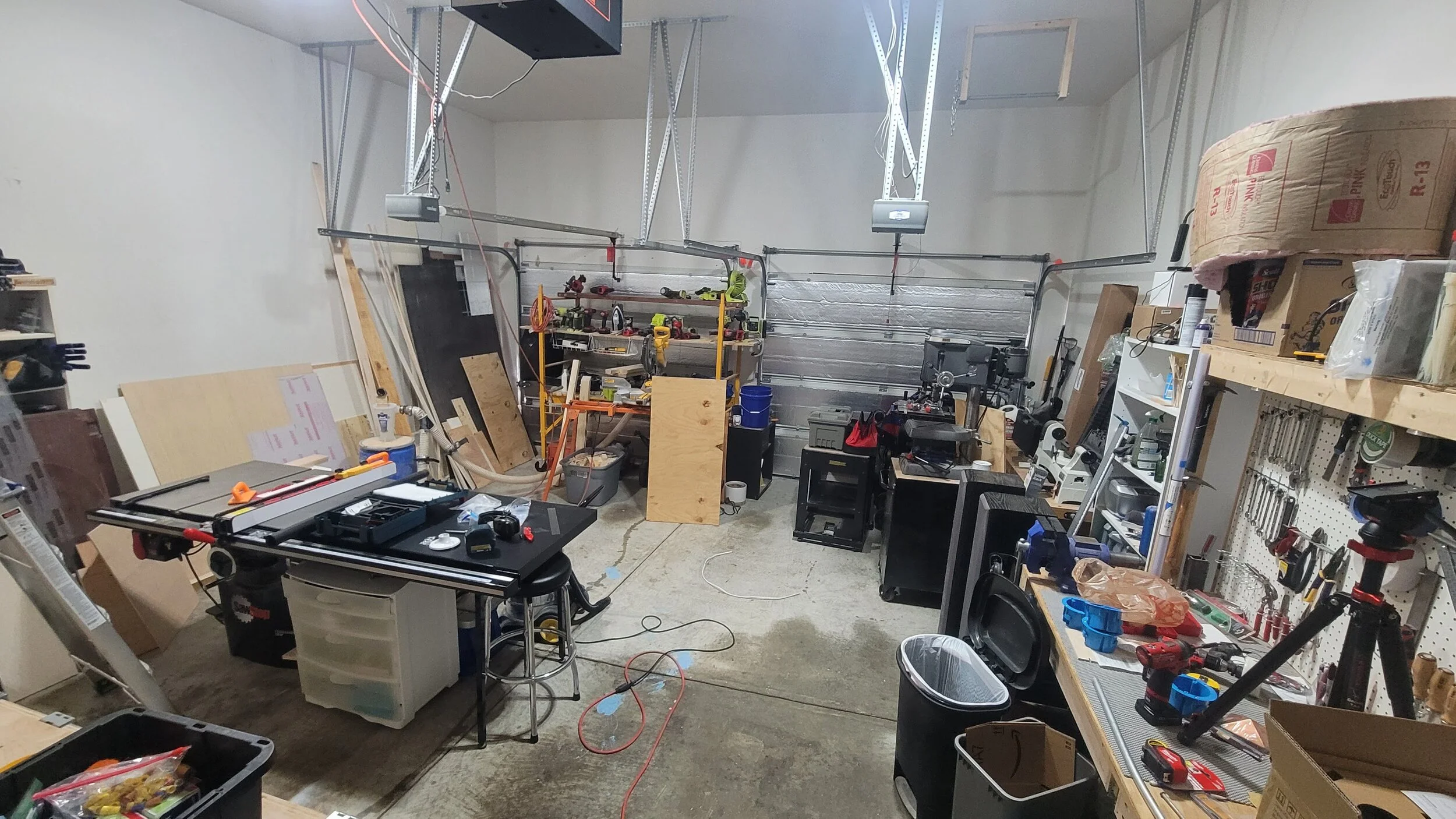
If you use your garage as a shop, you almost can’t have too much light. My garage lighting was decent but decent lighting doesn’t really cut it in a shop environment. The corners of the garage were pretty dark (good hiding places for monsters) and I found that on days when I spent long hours in the garage I was getting headaches from eye strain. There were also lots of shadows when my back was turned to the lights, which makes detail work difficult and interferes with the quality of my video recordings.
I had a few options for how to add the lights, but I thought that surface mounted boxes and metal conduit (EMT) would be the best option for a shop or garage environment.
Disclaimer: The following post contains affiliate links. If you purchase a product through one of the links, I may receive a small commission (at no cost to you) that I can use to feed the platypus. And it’s always hungry.
(most materials available at your local home improvement store)
LED Lights
Lighting Extension Box
Grounding Screws
1/2" Set-Screw Connectors
Push-In Wire Connectors
1/2" EMT Conduit
Drywall Anchors
Surface Mounted Ceiling Box
1/2" Strap Hangers
1" Hex Head Screws
14 Gauge Solid THHN Wire (Black and White)
Light Fixture Base
(in order of first use in the project)
Screwdrivers
Tongue and Groove Pliers
Pipe Cutter
Conduit Reamer
1/2" Conduit Bender
Stud Finder
Impact Driver
Fish Tape
Wire Strippers
Linesman's Pliers
When Brady and I first moved into this house, I quickly improved the lighting in the shop by replacing the existing lights with these 2 LED lights (linked in the materials list above). These lights helped a lot, but I’ve been looking forward to improving upon them for a while now!
I began by shutting off the power to the lights at the breaker and the switch controlling the lights, and removed the light from the fixture base. Then I took the existing light fixture down leaving the old wires sticking out.
The first thing we need to decide when doing this is how were going to bring the wires through the ceiling and into the surface mounted box so we can run conduit for the other lights. There are a few approaches to this which I’ll list below:
Remove the existing in-ceiling electrical box and patch the drywall. Then bring the Romex cables through a small hole in the drywall and install a surface mounted ceiling box on top of the drywall, securing the cables using a conduit clamp. This is probably the most robust option, but is also more work as you’ll need to repair the drywall first.
Install a square extension box (which for some reason is not sold in stores) on top of your existing in-ceiling electrical box and add a mud ring for the light fixture to mount to. The existing light box is likely attached to one of your ceiling joists that runs either perpendicular or parallel to your walls and using this extension box should put the knockouts in the box square to the walls (but be sure to check this before ordering!). I recommend this option for most people.
Install a lighting extension box (materials list). The way the mounting holes on the extension box are oriented will determine where the knockouts are. They’ll likely be at 45° to your walls, which makes bending the conduit more difficult and this is probably the worst option of the 3 for most people.
So of course, I picked option number 3.
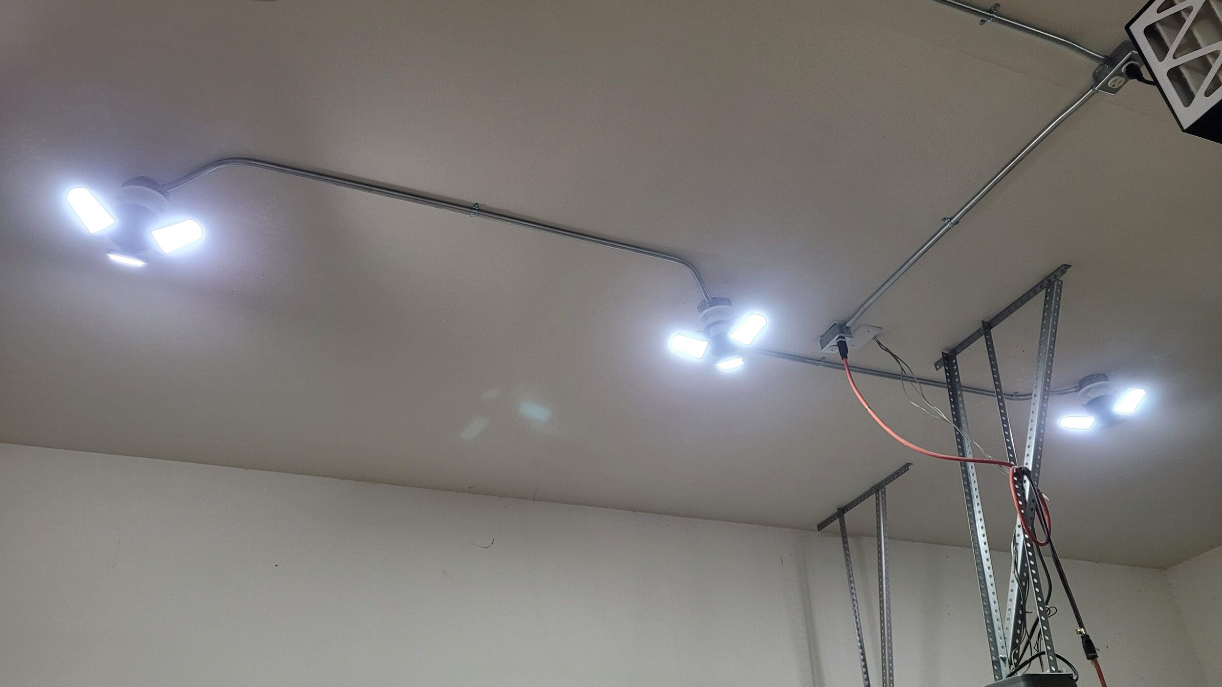
I have garage door opener outlets and mounting supports in between my existing light fixture and where I want to put the other lights and as I have to go around those anyway… I figured I’d just come out from the box, 45° bend back towards the other box, a long straight run, then a 45° bend back towards the other box. The picture below should give you an idea of what the heck I’m jabber jawing about.
I prepared the extension box by removing the 1/2” knockout plugs (it also has 3/4 knock out plugs, don’t remove those), hitting a screwdriver with a hammer to start the plug loose and then bending the plug back and forth with pliers until it broke free.
Extension boxes don’t come with a hole for a ground screw so I drilled and tapped a (10-32) hole for one. This lets the metal conduit raceway act as the ground so you don’t have to run a ground wire to each box through the conduit. It’s likely you don’t have metal taps to do this with so… to ground the circuits if you use an extension box you have a few options:
Use a grounding clip to ground the extension box. This is the easiest option, that is if the clip(s) don’t break when you’re trying to install them (a common problem in reviews)
Run a ground wire (green thhn or bare) to each box, like you would have to do if you were using pvc conduit. This ground needs to be the same gauge as the thickest gauge wire in any of the circuits running in the conduit
Run a single ground to the closest surface mounted box and attach it to the ground screw mounting point. All the connected metal conduit will then be grounded
I also added 1/2” set-screw connectors to the 1/2” knockouts on each side of the box. The easiest way to install these is to tighten the metal ring by hand with the set-screw about 1/4 turn away from the screw pointing straight up away from the fixture side of the box and then use a tongue and groove plier to grab the set-screw connector and tighten that an additional 1/4 turn. Since the locking ring was already snug and grabbing against the inside of the box it will stay in place and tighten the whole connector.
Once the extension box was fully prepared I mounted it loosely to the existing ceiling box. I added 4 port push-in wire connectors to the hot (black) and neutral (white) wires so that I can plug in the wires for the light on this fixture as well as the the other 2 lights that are going to be run off of this box. I also wrapped the ground wire around the ground screw and tightened it down (not pictured)
Once the box was up I marked where I wanted my other light locations (~5 feet in each direction) and then set about cutting and bending the metal conduit to run between the fixtures. Figuring out the length of conduit needed and bending conduit is a skill that’s too complicated to cover in detail in this post. Instead, I’ll give some tips about what I learned for this application and tell you how to install the fixtures still using metal conduit, but without needing to make any bends. If you have any questions, feel free to reach out in the comments at the bottom of this post!
I figured out the total length of my conduit after accounting for the various bends I needed (offsets, 45° turns) and cut it with a small pipe cutter. Thanks for letting me steal borrow the pipe cutter Dad!
Note: Things are about to get a little complicated and bendy but I promise I’ll explain the easier way to do this right after!
Cutting conduit with a pipe cutter leaves sharp burrs on the inside edge that need to be cleaned up so the insulation on the wires doesn’t get damaged as it’s pulled through. A conduit reamer like the one in the materials list is the correct tool to deburr this inside edge. I didn’t have one at the time so I spun the side of a 1/2” drill bit against the inside edge and that worked well as a substitute.
I marked my conduit on each end for all the bends I’m doing (lots of calculations go into figuring out where to put the marks). I put marks for the start and end of the box offset and one mark for the start of the 45° bend. Putting a zip tie around the conduit is an easy way to draw a circle all the way around at each mark.
To bend the box offset I put my first mark at the offset location in my bender and bent to just under 10°. Then I flipped the conduit over (180°) and bent another slightly less than 10° at the second mark. I found that putting the first mark at the end of the set-screw connector (5/8”) and the second 2 7/8” away from the first (3 1/2”) and using just under 10° bends results in good offsets for 1/2” conduit.
The box offset is necessary as the bottom edge of the conduit enters the box about a half inch above the base of the electrical box and without the offset the conduit would be about a 1/2 inch away from the ceiling/wall.
But wait! I told you I’d show you a way to do this without bends! And I’m no liar (hush platypus!)
You can use offset set-screw connectors instead of normal set-screw connectors to avoid needing to bend an offset. Using one of the square boxes mentioned earlier (options 1 and 2), making straight runs between boxes, and using the offset set-screw connectors will allow you to do this project without the need for bends. That does make the assumption that there is nothing in the path of where you want to put your conduit runs, which is often not the case…
If you don’t see yourself doing many conduit projects then the offset connectors are a good option. However, they’re a bit expensive and if you see yourself doing more conduit work in the future (as I did)… you probably ought to invest the time now and learn how to make offset bends.
Once I was done ranting about offset bends, I bent a 45° (perpendicular to the plane of the offset bends) to direct the conduit back towards the other light like I mentioned earlier. This is all a bit complicated but the good news is you probably don’t need to do it this way!
Then I mirrored the bends for the other end of the conduit.
If you do choose to learn to bend conduit I just want to say… buy extra conduit and be patient with yourself! I made tons of mistakes as I went and many times it took me screwing up a bend before I began to understand how it was supposed to be done. There are people that do this for a living and we are not them!
If you’re interested in learning to bend conduit more so than what’s covered in this post, here’s a good resource that I referenced often while I was learning.
I put my conduit in place between the extension box on the existing light fixture and a surface mounted box and lined up the surface mounted box with the mark I made earlier for the light fixture location. Then I marked the mounting holes in the surface mounted box. It’s fine if the box doesn’t fall right on top of the location mark you made earlier as long as its close.
I took the box down, installed drywall anchors on my marks, inserted the conduit back into the set-screw connectors (not pictured, but do this before screwing the box in place), and put the box back up adding washers to the screws that attach it to the drywall anchors.
I put the conduit up and used a stud finder to find the nearest joist and screwed in a strap hanger (and yes, I know I missed the first time!). I recommend using the 2 hole hangers for ceiling runs. To meet code, metal conduit must be secured at least every 10 feet and within 3 feet of every box.
Once the conduit was secured, I tightened the set-screw connectors at the box on each end.
I added another conduit run to the other side of the existing light fixture and secured the conduit and the other new box in place.
Then I ran a fish tape from the existing light box through to the new box and hooked on two 14 gauge thhn wires, one black and one white. You don’t really need a fish tape with only two wires and a run this short, you should be able to simply push the wires through the conduit (assuming solid not stranded thhn), but it does make things easier.
BE SURE to check the amperage of the circuit (printed on the breaker in the electrical panel) that controls your lights and use the correct gauge wiring! Most lights will be on 15 amp circuits (14 gauge wire), however it’s possible for them to be on a 20 amp circuits (12 gauge wire) so do not assume!
I pulled the wires through and bent them over the edge of the entry into the extension light box. You want around 6-8 inches of wire coming into the box.
I went to the surface mounted box end and cut the wires, again leaving 6-8 inches. Then I used wire strippers to remove the last 3/4 or so of insulation and bent hooks in the wires using lineman’s pliers to attach to the light fixture.
I hooked the wires over the screws (black to gold (hot), white to silver) and tightened them down. Be sure to orient the hooks so tightening the screw pulls the wires in further instead of pushing the wire out. There’s no ground needed for these particular light fixtures, but if it was needed I would have run a green thhn or bare wire from the ground screw in the box to the fixture
Then I bent the wires to fit in the box, slotted the fixture in place, and tightened the mounting screws. The light fixture bases are fragile, so don’t tighten too much and crack the base…
I repeated for the other new light, and then moved to the extension box to wire everything together. I plugged the two new hot wires (black) into the connector with the black wire and added a 4th short wire hooked at the end for the light fixture here. I then did the same for the neutral (white) wires.
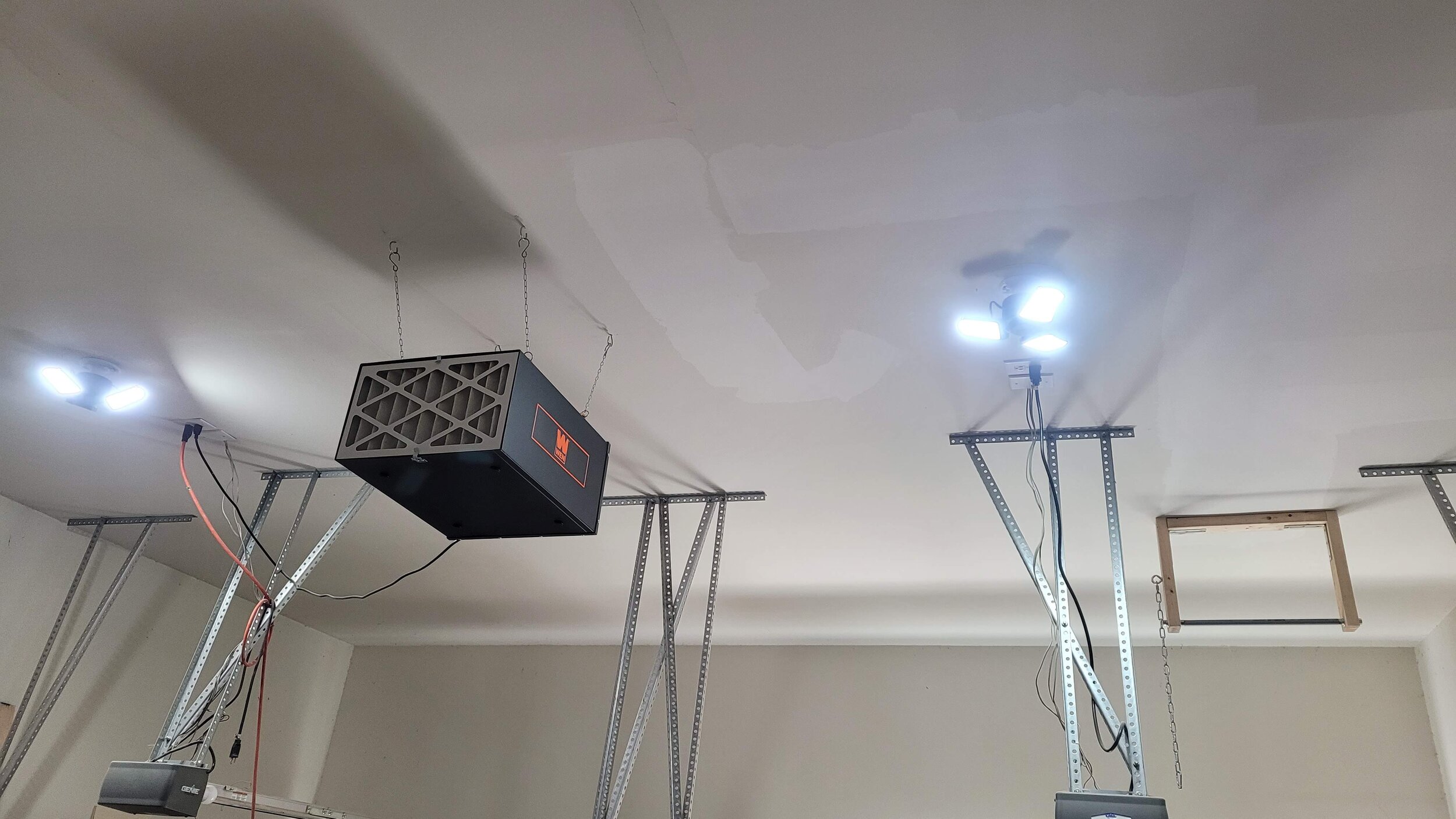
I added a light fixture base here as well and then screwed in the new lights. These lights are great for a shop since they replace a single bulb with a whole bunch of LEDs that you can adjust the angle on to make sure they’re aimed where you want
I added another two lights coming from the existing light on the other side of the garage and we’re done!
I hope this post brightened your day! All I know is it really shines some light on what a mess my garage is… ok ok I’m done with the word play. I’d add more but I want to keep this post [REDACTED] on puns.
You can look through the photos below to see a comparison. It’s not nearly as obvious a difference in the photos as it is in person but it’s super bright now! You can see a lot less shadows in the after photo which is a good representation of the light coverage.


I'd love to hear any questions or thoughts about adding the lights, bending conduit, etc. that you might have so be sure to let me know in the comments!
If you're not already subscribed to Project Billd content you can do that here and if you want to see more projects like this one be sure to check out my other projects on this site!
Until next time, Go Billd Yourself!
Don’t miss a thing!
Subscribe to get the latest content


